This code/library allows you to control LCD displays that are compatible with the DFRobot LCD Keypad Shield in arduino nano r3. There are many of them out there, and you can usually tell them by the 16-pin interface.
This example sketch prints “Hello World!” or “Your Name” to the LCD and shows the time in seconds since the Arduino was reset.
A register select (RS) pin that controls where in the LCD’s memory you’re writing data to. You can select either the data register, which holds what goes on the screen, or an instruction register, which is where the LCD’s controller looks for instructions on what to do next.
An Enable pin that enables writing to the registers
4data pins (D4 -D7). The states of these pins (high or low) are the bits that you’re writing to a register when you write, or the values you’re reading when you read.
There’s also a display constrast pin (Vo), power supply pins (+5V and Gnd) and LED Backlight (Bklt+ and BKlt-) pins that you can use to power the LCD, control the display contrast, and turn on and off the LED backlight, respectively.
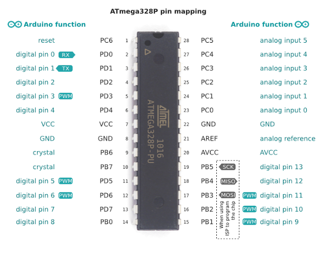
If u want to more porting Arduino and ATMEGA Pinout here :
i got the code from this and make some modification. The sampe code interfacing in C Embedded code is :
/****************************************************************************
LCD-AVR-4d.c - Use an HD44780U based LCD with an Atmel ATmega processor
Copyright (C) 2013 Donald Weiman (weimandn@alfredstate.edu)
This program is free software: you can redistribute it and/or modify
it under the terms of the GNU General Public License as published by
the Free Software Foundation, either version 3 of the License, or
(at your option) any later version.
This program is distributed in the hope that it will be useful,
but WITHOUT ANY WARRANTY; without even the implied warranty of
MERCHANTABILITY or FITNESS FOR A PARTICULAR PURPOSE. See the
GNU General Public License for more details.
You should have received a copy of the GNU General Public License
along with this program. If not, see <http://www.gnu.org/licenses/>.
*/
/****************************************************************************
File: LCD-AVR-4d.c
Date: September 16, 2013
Target: ATmega328
Compiler: avr-gcc (AVR Studio 6)
Author: Donald Weiman
Summary: 4-bit data interface, busy flag not implemented.
Any LCD pin can be connected to any available I/O port.
Includes a simple write string routine.
*/
/******************************* Program Notes ******************************
This program uses a 4-bit data interface but does not use the
busy flag to determine when the LCD controller is ready. The
LCD RW line (pin 5) is not connected to the uP and it must be
connected to GND for the program to function.
All time delays are longer than those specified in most datasheets
in order to accommodate slower than normal LCD modules. This
requirement is well documented but almost always ignored. The
information is in a note at the bottom of the right hand
(Execution Time) column of the instruction set.
***************************************************************************
The four data lines as well as the two control lines may be
implemented on any available I/O pin of any port. These are
the connections used for this program:
----------- ----------
| ATmega328 | | LCD |
| | | |
| PD7|---------------->|D7 |
| PD6|---------------->|D6 |
| PD5|---------------->|D5 |
| PD4|---------------->|D4 |
| | |D3 |
| | |D2 |
| | |D1 |
| | |D0 |
| | | |
| PB1|---------------->|E |
| | GND --->|RW |
| PB0|---------------->|RS |
----------- ----------
**************************************************************************/
#define F_CPU 16000000UL
#include <avr/io.h>
#include <util/delay.h>
// LCD interface (should agree with the diagram above)
// make sure that the LCD RW pin is connected to GND
#define lcd_D7_port PORTD // lcd D7 connection
#define lcd_D7_bit PORTD7
#define lcd_D7_ddr DDRD
#define lcd_D6_port PORTD // lcd D6 connection
#define lcd_D6_bit PORTD6
#define lcd_D6_ddr DDRD
#define lcd_D5_port PORTD // lcd D5 connection
#define lcd_D5_bit PORTD5
#define lcd_D5_ddr DDRD
#define lcd_D4_port PORTD // lcd D4 connection
#define lcd_D4_bit PORTD4
#define lcd_D4_ddr DDRD
#define lcd_E_port PORTB // lcd Enable pin
#define lcd_E_bit PORTB1
#define lcd_E_ddr DDRB
#define lcd_RS_port PORTB // lcd Register Select pin
#define lcd_RS_bit PORTB0
#define lcd_RS_ddr DDRB
// LCD module information
#define lcd_LineOne 0x00 // start of line 1
#define lcd_LineTwo 0x40 // start of line 2
//#define lcd_LineThree 0x14 // start of line 3 (20x4)
//#define lcd_lineFour 0x54 // start of line 4 (20x4)
//#define lcd_LineThree 0x10 // start of line 3 (16x4)
//#define lcd_lineFour 0x50 // start of line 4 (16x4)
// LCD instructions
#define lcd_Clear 0b00000001 // replace all characters with ASCII 'space'
#define lcd_Home 0b00000010 // return cursor to first position on first line
#define lcd_EntryMode 0b00000110 // shift cursor from left to right on read/write
#define lcd_DisplayOff 0b00001000 // turn display off
#define lcd_DisplayOn 0b00001100 // display on, cursor off, don't blink character
#define lcd_FunctionReset 0b00110000 // reset the LCD
#define lcd_FunctionSet4bit 0b00101000 // 4-bit data, 2-line display, 5 x 7 font
#define lcd_SetCursor 0b10000000 // set cursor position
// Program ID
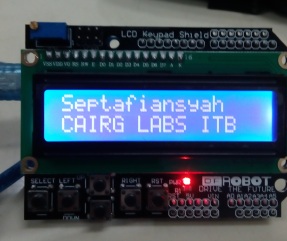
uint8_t program_author[] = "Septafiansyah";
uint8_t program_version[] = "CAIRG LABS ITB";
uint8_t program_date[] = "Aug, 09 2016";
// Function Prototypes
void lcd_write_4(uint8_t);
void lcd_write_instruction_4d(uint8_t);
void lcd_write_character_4d(uint8_t);
void lcd_write_string_4d(uint8_t *);
void lcd_init_4d(void);
/******************************* Main Program Code *************************/
int main(void)
{
// configure the microprocessor pins for the data lines
lcd_D7_ddr |= (1<<lcd_D7_bit); // 4 data lines - output
lcd_D6_ddr |= (1<<lcd_D6_bit);
lcd_D5_ddr |= (1<<lcd_D5_bit);
lcd_D4_ddr |= (1<<lcd_D4_bit);
// configure the microprocessor pins for the control lines
lcd_E_ddr |= (1<<lcd_E_bit); // E line - output
lcd_RS_ddr |= (1<<lcd_RS_bit); // RS line - output
// initialize the LCD controller as determined by the defines (LCD instructions)
lcd_init_4d(); // initialize the LCD display for a 4-bit interface
// display the first line of information
lcd_write_string_4d(program_author);
// set cursor to start of second line
lcd_write_instruction_4d(lcd_SetCursor | lcd_LineTwo);
_delay_us(80); // 40 uS delay (min)
// display the second line of information
lcd_write_string_4d(program_version);
// endless loop
while(1);
return 0;
}
/******************************* End of Main Program Code ******************/
/*============================== 4-bit LCD Functions ======================*/
/*
Name: lcd_init_4d
Purpose: initialize the LCD module for a 4-bit data interface
Entry: equates (LCD instructions) set up for the desired operation
Exit: no parameters
Notes: uses time delays rather than checking the busy flag
*/
void lcd_init_4d(void)
{
// Power-up delay
_delay_ms(100); // initial 40 mSec delay
// IMPORTANT - At this point the LCD module is in the 8-bit mode and it is expecting to receive
// 8 bits of data, one bit on each of its 8 data lines, each time the 'E' line is pulsed.
//
// Since the LCD module is wired for the 4-bit mode, only the upper four data lines are connected to
// the microprocessor and the lower four data lines are typically left open. Therefore, when
// the 'E' line is pulsed, the LCD controller will read whatever data has been set up on the upper
// four data lines and the lower four data lines will be high (due to internal pull-up circuitry).
//
// Fortunately the 'FunctionReset' instruction does not care about what is on the lower four bits so
// this instruction can be sent on just the four available data lines and it will be interpreted
// properly by the LCD controller. The 'lcd_write_4' subroutine will accomplish this if the
// control lines have previously been configured properly.
// Set up the RS and E lines for the 'lcd_write_4' subroutine.
lcd_RS_port &= ~(1<<lcd_RS_bit); // select the Instruction Register (RS low)
lcd_E_port &= ~(1<<lcd_E_bit); // make sure E is initially low
// Reset the LCD controller
lcd_write_4(lcd_FunctionReset); // first part of reset sequence
_delay_ms(10); // 4.1 mS delay (min)
lcd_write_4(lcd_FunctionReset); // second part of reset sequence
_delay_us(200); // 100uS delay (min)
lcd_write_4(lcd_FunctionReset); // third part of reset sequence
_delay_us(200); // this delay is omitted in the data sheet
// Preliminary Function Set instruction - used only to set the 4-bit mode.
// The number of lines or the font cannot be set at this time since the controller is still in the
// 8-bit mode, but the data transfer mode can be changed since this parameter is determined by one
// of the upper four bits of the instruction.
lcd_write_4(lcd_FunctionSet4bit); // set 4-bit mode
_delay_us(80); // 40uS delay (min)
// Function Set instruction
lcd_write_instruction_4d(lcd_FunctionSet4bit); // set mode, lines, and font
_delay_us(80); // 40uS delay (min)
// The next three instructions are specified in the data sheet as part of the initialization routine,
// so it is a good idea (but probably not necessary) to do them just as specified and then redo them
// later if the application requires a different configuration.
// Display On/Off Control instruction
lcd_write_instruction_4d(lcd_DisplayOff); // turn display OFF
_delay_us(80); // 40uS delay (min)
// Clear Display instruction
lcd_write_instruction_4d(lcd_Clear); // clear display RAM
_delay_ms(4); // 1.64 mS delay (min)
// ; Entry Mode Set instruction
lcd_write_instruction_4d(lcd_EntryMode); // set desired shift characteristics
_delay_us(80); // 40uS delay (min)
// This is the end of the LCD controller initialization as specified in the data sheet, but the display
// has been left in the OFF condition. This is a good time to turn the display back ON.
// Display On/Off Control instruction
lcd_write_instruction_4d(lcd_DisplayOn); // turn the display ON
_delay_us(80); // 40uS delay (min)
}
/*...........................................................................
Name: lcd_write_string_4d
; Purpose: display a string of characters on the LCD
Entry: (theString) is the string to be displayed
Exit: no parameters
Notes: uses time delays rather than checking the busy flag
*/
void lcd_write_string_4d(uint8_t theString[])
{
volatile int i = 0; // character counter*/
while (theString[i] != 0)
{
lcd_write_character_4d(theString[i]);
i++;
_delay_us(80); // 40 uS delay (min)
}
}
/*...........................................................................
Name: lcd_write_character_4d
Purpose: send a byte of information to the LCD data register
Entry: (theData) is the information to be sent to the data register
Exit: no parameters
Notes: does not deal with RW (busy flag is not implemented)
*/
void lcd_write_character_4d(uint8_t theData)
{
lcd_RS_port |= (1<<lcd_RS_bit); // select the Data Register (RS high)
lcd_E_port &= ~(1<<lcd_E_bit); // make sure E is initially low
lcd_write_4(theData); // write the upper 4-bits of the data
lcd_write_4(theData << 4); // write the lower 4-bits of the data
}
/*...........................................................................
Name: lcd_write_instruction_4d
Purpose: send a byte of information to the LCD instruction register
Entry: (theInstruction) is the information to be sent to the instruction register
Exit: no parameters
Notes: does not deal with RW (busy flag is not implemented)
*/
void lcd_write_instruction_4d(uint8_t theInstruction)
{
lcd_RS_port &= ~(1<<lcd_RS_bit); // select the Instruction Register (RS low)
lcd_E_port &= ~(1<<lcd_E_bit); // make sure E is initially low
lcd_write_4(theInstruction); // write the upper 4-bits of the data
lcd_write_4(theInstruction << 4); // write the lower 4-bits of the data
}
/*...........................................................................
Name: lcd_write_4
Purpose: send a byte of information to the LCD module
Entry: (theByte) is the information to be sent to the desired LCD register
RS is configured for the desired LCD register
E is low
RW is low
Exit: no parameters
Notes: use either time delays or the busy flag
*/
void lcd_write_4(uint8_t theByte)
{
lcd_D7_port &= ~(1<<lcd_D7_bit); // assume that data is '0'
if (theByte & 1<<7) lcd_D7_port |= (1<<lcd_D7_bit); // make data = '1' if necessary
lcd_D6_port &= ~(1<<lcd_D6_bit); // repeat for each data bit
if (theByte & 1<<6) lcd_D6_port |= (1<<lcd_D6_bit);
lcd_D5_port &= ~(1<<lcd_D5_bit);
if (theByte & 1<<5) lcd_D5_port |= (1<<lcd_D5_bit);
lcd_D4_port &= ~(1<<lcd_D4_bit);
if (theByte & 1<<4) lcd_D4_port |= (1<<lcd_D4_bit);
// write the data
// 'Address set-up time' (40 nS)
lcd_E_port |= (1<<lcd_E_bit); // Enable pin high
_delay_us(1); // implement 'Data set-up time' (80 nS) and 'Enable pulse width' (230 nS)
lcd_E_port &= ~(1<<lcd_E_bit); // Enable pin low
_delay_us(1); // implement 'Data hold time' (10 nS) and 'Enable cycle time' (500 nS)
}
Output code :
Refrence and many thanks to:
- http://web.alfredstate.edu/weimandn/programming/lcd/ATmega328/LCD_code_gcc_4d.html
- http://www.dfrobot.com/wiki/index.php?title=Arduino_LCD_KeyPad_Shield_(SKU:_DFR0009)
- https://www.arduino.cc/en/Tutorial/HelloWorld

Ngelondo pasih banget..emejing kakaaak
hahahah tadinya mau bahasa sansekerta cuma kagak bisa